N3OX 3m Flex Vertical, a Short, Frequency Agile Vertical

[Home]
[Shack]
[Projects]
[Tech Topics]
Introduction
This project is a practical tunable short antenna, but it's also intended to make a statement. Too many published projects involving electrically-small antennas fail to justify their performance claims with objective modeling or data. Worse, they frequently appeal to "new physics" or "undiscovered" principles to establish the novelty and advantages of the antenna design.
Electromagnetic engineering is a mature field. Careful theoretical analysis or real-world comparative testing of any design will reveal its true performance and allow proper comparison to full-size antennas. But the designers of small antennas routinely fail to justify their designs with measurements or theory, and tend toward overly-complex designs that make third-party analysis impractical.
I wanted to do something different here. This antenna's operating principles are easily explained using well-tested physical and RF engineering principles. It is straightforward to numerically model this design with accessible NEC-2 modeling tools. From an electromagnetic standpoint the antenna is familiar and easy to understand, and I think there is substantial value in that. Ultimately, this is an old design: a monopole loaded with a capacitance hat and lumped inductor. But I've put a novel mechanical twist on this antenna that has clear practical advantages, beause I wanted to share something different without trying to baffle you.
In addition to describing a small antenna that works well, I want to provide reproducible evidence that it works well and demonstrate some meaningful measurements done with equipment you might already have. It's easy to be over-awed by the equipment and procedure that goes into a good, controlled experiment like N6LF's series of ground radial experiments. It's nice to have a vector network analyzer to do this sort of thing. It would speed things along. But a lot of what's important to a good study like N6LF's is the procedure as much as the tools, and good procedure only requires time and practice. The measurements I did are the kind of thing that anyone can do with a litle setup if they'd like to satisfy their skepticism about a new design. With a little care (and healthy self-skepticism so you don't fool yourself), they're vastly more precise than trying to assess an antenna over the air. If you are set up to do measurements, it means you can modify and redesign the antenna and still remain confident that it's working well.
What to build?
General Principles
So, fine. I've decided that I need a pretty small antenna, and that I want some kind of straightforward, reliable design. But WHAT can I build? There is ample good information out there on how to make good small antennas, in books and even on the web. There are pages that have fairly general advice with solid engineering analysis on how to build good small loaded antennas, like some of the pages on W8JI's Website. There is a fair amount of specific construction information for certain types of antennas, like the very popular magnetic loop out there. AA5TB's Website is a great jumping off point for that.
If you stick to technically accurate sites and books and study the general principles of electrically small antennas, you'll know that there is a fundamental tradeoff among three things:
- Efficiency
- Bandwidth
- Physical Size
However, because the amateur bands have large fractional bandwidth, even if you manage Q well, you generally give up full-band coverage when you shrinking an antenna. It is well-known that you should expect narrow usable bandwidth from an efficient fixed-tuned small antenna.
These are very important general principles, and for any given type of antenna, it can be clear how to do that. But there are a lot of designs available. How to choose?
What About a Magnetic Loop?
Among homebrewers, the magnetic loop seems to be one of the the most popular small antenna projects that are based on solid physical principles. I've got one. It's clear how to build one one well. When you build a magnetic loop, you should build it as big as is practical, you should solder or weld the joints, and you should use a very high quality transmitting capacitor. You can do pretty well that way.
But there's a weird problem that's been nagging at me. The magnetic loop most definitely does not maximize radiation resistance. Not even close. The enormous currents in typical magnetic loops, 100+ amps for the brave souls who try them at kilowatt power levels on the lower bands, are due to the fact that the radiation resistance of the magnetic loop is really tiny. The current going "up" on one side of the loop at one instant in the RF drive cycle is nearly totally cancelled by the current going "down" in the diametrically opposite point. The currents cancel perfectly in the broadside directions of the loop, giving deep nulls. There's a tiny phase delay from one side of the loop to the other for radiation leaving in the plane of the loop, and that's what does all the radiation. But you need huge currents to radiate even a small amount of power.
The practical upshot of this is that you need to make the antenna of very low loss stuff, like copper pipe, and you need to use a very low resistance capacitor to tune it to resonance. You also need to use a very, very high voltage capacitor for just 100W, and if you want to run higher power, you soon have no choice besides buying a $200 or more vacuum variable capacitor. The operational bandwidth of a magnetic loop is quite tiny at one tuning setting, to the point where some people have built loops for 160m or 80m that barely pass a single SSB signal. But they remain very popular among the homebrew crowd.
Why Magnetic Loops?
Why do people routinely put up with low power handling, field cancellation, expensive materials, an expensive capacitor, and the need to constantly retune when you change frequency even a few kHz on a low HF band?I think one of the reasons is this: We're not single-frequency broadcasters and the magnetic loop has continuous tuning that can easily be remotely controlled. Who really cares if you have a 3kHz 2:1 VSWR bandwidth on 40m if that bandwidth can move anywhere in the 40m band? Who cares if the tuning all changes down 100kHz when it rains or snows? The tunability completely removes the bandwidth restriction and lets you compensate for the environment.
Sure, you can build a fixed-tuned dipole or vertical type antenna with 50kHz of bandwidth on 80m, but if you always have to run outside with your antenna analyzer any time the antenna gets damp to re-tune it, you're going to go nuts.
Variable Inductors
Continuous tuning can also be achieved by a home station antenna that's based around a screwdriver-type tunable inductor. But a screwdriver antenna is a low-volume custom manufactured part that's generally more expensive than a vacuum variable. It's even worse if you want independence from ground radials and want to build a dipole with TWO coils. Not to mention that it might not feel like so much of a homebrew project if you just order a couple of beautifully made Scorpion screwdriver antennas. Roller inductors will probably move you around a couple bands, and certainly let you move around inside a band, but they seem a little hard to find and I don't want to try to keep a rolling contact working outdoors. Furthermore, it seems quite difficult to build a reliable adjustable inductor at home even for low power, and people who want to build low power magnetic loops have several good options for homebrew capacitors.
What Else?
I have a magnetic loop already, and wanted to try something that would have higher radiation resistance while keeping some of the frequency-agile convenience.So what design goals did I have in mind when I came up with this antenna?
- High radiation resistance for the size, suggesting a dipole-type antenna with heavy end loading.
- Ordinary coils and capacitance hats to demonstrate a particularly simple, proven type of antenna.
- Some measure of continuous tuning, in particular I wanted enough to cover the entire 40m band including some extra for WX drift.
- The continuous tuning should be easily remote controlled, as easy or easier than a magnetic loop.
- No expensive special components. I'm fond of designing antennas that you could build from stuff you found at Home Depot.
- Cover a good number of bands.
- Go small, but not absurdly small, to keep performance very high and demonstrate that "full size or go home" is not reasonable advice.
N3OX Three Meter Flex Vertical - Design and Construction
Since I planned to start with a dipole, the antenna wasn't necessarily intended to be a homage to Jerry Sevick, W2FMI, but it kind of turned out that way. I've always wanted to try something like his six foot 40m vertical, but never got around to it. In the end this antenna is pretty similar, though it actually is about ten feet (3m) tall (0.075λ on 40m) because the capacitance hat is a tall pyramid shape. The model schematic from EZNEC on the right below shows the parts of the antenna that are electrically conducting. My version, depicted on the left, has a 76 inch vertical part made of tubing from DX Engineering and a wire pyramid capacitance hat supported on four 3/16" diameter 4 foot long fiberglass rods from Max Gain Systems.


The finished antenna (left) and a schematic of the simple model geometry (right).
The antenna is loaded to resonance by the large capacitance hat and a conventional high Q inductor wound on a machined PVC coil form pictured below. The coil is mounted to a short piece of fiberglass tube which also provides a strong joint betwen the two tubing sections about 2/3rds of the way up from the base. I realize the kind of fancy construction of these parts is not in keeping with the claim I made about "simple materials," but I intended this antenna to be a keeper and I decided to spend some money and spend some time in the machine shop with the lathe. A nice way to make coils without that facility can be found on AD5X's Website under "Build your own air-wound coils and coil supports." The strong fiberglass insulator is overkill given the likely forces on this short antenna. You could make this out of EMT tubing and PVC pipe, or all PVC with a wire radiator, and coils like AD5X suggests.
IMPORTANT: You might consider the use of several wires in
parallel, like a "cage" radiator if
you use a PVC and wire construction. I ran some more recent models and
thinner wire or tubing than my 1.25" tubing requires a larger loading
coil for resonance. A larger loading coil means more loss resistance
and a narrower operating bandwidth.
If you
can find thin
fiberglass driveway markers or
suitable fishing rod parts you might really be able to make a version of locally sourced parts.
The coil has too many turns for 40m on the final antenna, but has too few turns for
60m. I can get down to 5.6MHz if I tap at the top, so probably
17 or 18 turns 10AWG 4TPI on a 3.5" PVC pipe or slightly
compressing a coil that can slide would get you on 60m without
giving up 20m. The coil should actually be closer to the
capacitance hat for optimum radiation resistance. Its location
was set in a prior design iteration but I didn't move it
hatward because the modeled improvement didn't seem worth
rebuilding that part.

Loading coil with PowerPole taps for 20m, 30m, and 40m. Coil is 16 turns 10AWG, 4 turns per inch on a 3.5 inch PVC pipe.
On 40m, the antenna's 2:1 VSWR bandwidth is about 73kHz. But that 73kHz bandwidth can be tuned all the way up and down the band. Four ropes are connected to the midpoint of each of the horizonatal wires in the capacitance hat, and when those four ropes are pulled by a common rope that goes down inside the vertical tubing, the fiberglass support rods bend, and the hat collapses in on itself. The slightly smaller hat raises the resonant frequency of the antenna. The photos below show it tuned to different frequencies. I don't recall the full tuning range, but it's something like 6.95MHz to maybe as high as 8MHz when the fiberglass rod tips are nearly touching. Since this antenna handles high power and can be tweaked easily for an ultra-low SWR at every frequency it would be a good choice to pair with a solid-state amplifier. No high power tuner needed.


The capacitance hat when the antenna is tuned to the low end of the range (left) and higher in the range (middle).
Another shot of the partially collapsed capacitance hat is shown below. You might note that the Q of the antenna is a bit higher at the higher end of the band because the capacitance is less and the inductance stayed the same, and I can just detect that in the measured 2:1 VSWR bandwidth. I think I get closer to 75kHz at the bottom of 40m and 72kHz at the top. The whole antenna is pretty low Q for the size because of the big hat, so it can efficiently cover a wide bandwidth. Among other things, this means that the tuning isn't touchy.

Partially collapsed capacitance hat from the side


The capacitance hat spoke hub with ropes (left) and the end of the fiberglass pull rod that reaches from the ropes to down to below the coil (right).
Below is a short video of the hat in operation.
When I originally envisioned this antenna, I figured I'd use some kind of motor reel to wind up the rope, and I think that could be a cool thing allowing computer controlled tuning. But for testing, I set up the simplest possible remote control. I ran the rope out the bottom of the vertical (running over the edge of the DX Engineering Resin Support Block insulator, not the sharp edge of the aluminum), and then just ran the rope back to the shack through a snug fitting hole in my cable entrance panel. Sweet and simple. Shown below is the pull rope and some added elastic cord tied to the base of the vertical and tied to the rope. This gives a better pull-back for the rope lying in the grass. The fiberglass rods have plenty of pull if you don't use a very long "remote rope" but the elastic helps get the hat back to maximum expansion when the "remote rope" is long. To hold the tuning fixed once I've tuned it, I just hitch the rope to a support arm under one of the radios on my desk. No kidding. It's like the exact polar opposite of my last remote control project, but sometimes a simple system is the best system for the job. Right now I don't have a remote tap changer, and I just go outside to change bands, but something with relays would be easy to cook up. I've mostly been using the antenna on 40m where it's electrically smallest, because that's really the main point of these experiments. The other bands should work even better than 40m.

Tuning rope with elastic pull-back assist.
The initial model runs using perfect ground suggested a radiation resistance around 5.4 ohms, and it seems that my coil and my radial field, 27 radials out to the edges of an approximately 50 by 50 foot area, only add a little to that number. The antenna base impedance is about 6 ohms at resonance. I matched it to the coax using a shunt inductor across the feedpoint, with about 0.43μH needed.

Radial connection, base insulators and feedpoint shunt matching coil, 6 turns 10AWG on a 1 inch diameter, about 2 inches long.
Measurements and Model Comparisons
The easiest and first comparison is impedance and VSWR vs. the model. Here I'm presenting the measurements and models including the parallel transformation with the shunt matching coil. Since I predicted a radiation resistance of 5.4 ohms and measured 6 ohms I added 0.6 ohms to the loading coil in the model, and I calculated these model data using MININEC type ground which is lossless in the near field. The model with just 6 ohms total resistance and a 0.43μH shunt seems to reproduce the measured impedance data well. We won't trust the 5.4 ohm radiation resistance number to calculate the efficiency, however. That implies just 0.5dB loss with respect to a quarter wave vertical and I'll show later that -0.5dB vs. a 1/4λ seems too optimistic. If I put in "realistic" radials into the model, and use Sommerfeld-Norton "High Accuracy" ground, it doesn't properly predict the impedance, VSWR curves, etc.

Measured and modeled resistance and reactance with the shunt coil installed.
There are many tricky issues in the model/measurement comparison. The radiation resistance from a short vertical has an important contribution from its image in the ground. Over perfectly conducting ground (or MININEC, which is also perfectly conducting in the nearfield) the radiation resistance of a short monopole is doubled vs. its free space value (here, 5.4 ohms perfect ground, 2.7 ohms free space). The data and models suggest that it's not quite doubled over real earth, but the Sommerfeld Norton models for realistic ground parameters don't agree with reality in terms of losses and base impedance. The details of this need their own article, however. We will not be relying on model/measurement comparisons to infer the antenna's efficiency, though the comparisons here do suggest a fairly low loss antenna.
The measured and modeled SWR curve is given below for the same measurement data. This is probably a more useful curve for would-be builders. The agreement is good, and I consistently get a 2:1 VSWR band width between 72kHz and 75kHz at any one tuning setting. This is nice, because it doesn't require particularly frequent retuning, and it can rain and blow around the antenna a bit without knocking the SWR for a loop.

Measured and modeled SWR curve with the shunt coil installed.
The measured impedance data already suggest good agreement with the model. However, there is a lot of value in measuring exactly what you want to know, which in this case, is a gain or efficiency comparison against a reasonable reference antenna. The natural choice for a comparison here was a simple 1/4λ vertical. I made one from 18AWG wire wound on the outside of a Spiderbeam fiberglass pole, which was easy to take up and down. The reference antenna was resonant around 7300kHz not far from the testing frequency. It had a base impedance of about 26 ohms at resonance, which I matched to nearly 50 ohms using a series section transformer identical to the one on the bottom of this page. Both antennas need to be matched to 50 ohms for this technique to work easily, but I already did that anyway.

Simple reciprocal test setup for relative field strength measurements.
To simplify the necessary equipment and speed the data collection, I chose to measure the difference between the antennas on reception by using a small battery powered oscillator a certain distance away from the antennas under test, as pictured above. I used a battery powered TTL clock oscillator, pictured below, at the feedpoint of a six foot high vertical dipole. There's some other circuitry, there but it's not needed. I used the fourth harmonic of an 1843.2kHz oscillator to test the antenna just above the 40m band. An adjustable attenuator on the input of the radio is useful to set the level of received signal such that there is no distortion in any receiver stage. However, a large value of attenuation should be used to terminate the feedline at the receiver. It is important that the SWR on the line is low when the antenna is the "source" and the line and receiver are the "load" as in this test. The RX input impedance is not necessarily 50 ohms, and mismatch to the line will cause extra losses in the received signal, and uncertainty in signal measurements when two different lines are used (as in this case). In some cases this attenuator is not needed but it's good insurance.
In my case about 40dB of attenuation gave a good signal to noise ratio without any gain compression or distortion in the receiver. It is important to disable the AGC or operate at a signal level below the onset of AGC action where the reciever's RF input and audio output are linearly related. I simply used a multimeter on AC voltage mode to measure the receiver's audio output voltage when each antenna was connected. I used CW mode with a narrow filter to increase the signal to noise ratio. The meter I used was just an ordinary DMM from Radio Shack. Not fancy, but I checked its response at several different audio frequencies and amplitudes using some synthesized tones from my computer.

Battery powered "pinger" based on a digital clock oscillator at 1843.2kHz. I used the fourth harmonic just above the 40m band at 7372.8MHz.
The test procedure involved setting up one antenna, measuring its voltage at the receiver, taking it down, and setting up the other antenna. This substitution is somewhat time consuming if you don't think it through, but it is the best way to get good results on a small lot. It eliminates the chances of the two antennas under test influencing each other. It also helps you get a handle on your random errors because you're repeatedly comparing each antenna to itself taken down and put up again. If the antenna is especially touchy, like it has a radiating feedline, you'll see this in the wildly varying results of one antenna against itself. In my tests, this was not a problem. For a fixed source location, the measured voltages on one antenna over three trials usually fell within the range over which the voltmeter was fluctuating for any one trial. If you do these tests and get 0.17V/0.29V/0.08V for trial one/two/three on the same antenna, you know you're changing something you didn't intend to change, and you can do experiments to discover what it is. If you experiment this way, your procedure is self-correcting and gets better and better with time. My results were more typically like 0.26V/0.26V/0.27V for Antenna 1 and 0.34V/0.34V/0.34V for Antenna 2 with perhaps ±0.005V fast fluctuations as I took down and put the same antennas up three different times. You don't have to guess at your measurement and "uncontrolled variable" errors if you do many trials. They will just show up in the data. You can make tiny changes to things that should be "unimportant" and see what happens. If they're really unimportant, nothing at all will happen.
To get an idea of how much the clutter in my yard mattered to the results, I also I tested the relative signal level with the source at many locations around my yard, in proximity to different obstacles, like my nearly 30 foot mast under my 20m Moxon. The measurement locations are depicted below.

Field strength locations with respect to A.U.T. (Blue dot in center of radials)).
Locations 1 through 5 had the center of the 6 foot source dipole about 9 feet off the ground on a fiberglass fishing pole. Location 6 had the dipole center about 34 feet in the air. Locations 1 through 5 were done one day, location 6 was done the next day. Locations 1, 2 and 3 were measured closely with a tape measure so that the source support pole was 24.5 feet from the antenna. The horizontal distance to locations 4,5, and 6 were measured using Google Earth to be 47, 40, and 72 feet respectively. At several locations, I switched antennas several times for the sake of checking and quantifying the inevitable random errors. I returned to location #1 at the end of the first day's trials to check for long-term drift.
I converted the recorded voltages to a decibel difference:

The results for twelve trials are shown below, annotated according to the aerial photo above.

Raw field strength directly taken from relative voltage measurements, annotated by measurement location.
This is already rather useful information. All the raw measurements have the ten foot antenna no worse than 2.2dB or so from a full size quarterwave! I think that's a good deal better than telling you that I worked V55V on it. But it's not the end of the story. Unfortunately I am not able to actually get the signal source out to a reasonable far field distance here. That means I am making near field measurements, and the expected field strength differential will not necessarily be the same at all distances. The far field pattern of the quarter wave and the short antenna are nearly identical, but this is not the case in the near field. The question, then, is what DO we expect?

A direct model of the field strength test procedure to help interpret the near field results.
We can attempt to answer that with antenna modeling. Depicted above is a model with a 50 ohm load at the feedpoint of the matched vertical, excited with a six foot whip at 24.5 feet out and center 9 feet up. This is a model of the actual test procedure in locations 1, 2, and 3. First I modeled the far field gain differential of the two antennas over the same radial field. Then I modeled the voltage delivered across a 50 ohm load at each antenna's matched feedpoint, exactly what I'm measuring at the receiver input. I did this for both antennas at each measurement location, and developed a set of corrections to map the near field measurements to equivalent far field measurements. In locations #1, #2, and #3, the near field measurement will make the short vertical appear 0.4dB better than it is in the far field. So in locations 1,2, and 3, I subtracted 0.4dB from the actual measurements. At location #4, the near field measurement predicts that the short vertical will appear 0.3dB worse than it is, so I added 0.3dB to location 4. I needed to add 0.14dB for location 5 and location 6 had the largest error between near and far field even though it was furthest away. The model predicts that the short vertical will appear 1.1dB worse than it is in the far field at location 6, so I added 1.1dB. The results of the near field measurements converted to equivalent far field gain difference are shown below:

Field strength measurements corrected to take the predicted variations into account.
The corrections based on the expected near field comparisons tighten up the measurements a bit, especially the ones taken in front of the house. Test #5 was certainly especially down, but this location was close to the aluminum-sided house and completely in the shadow for short wavelength waves. It shouldn't be much of a "shadow" for 7MHz waves, and I'm not going to do a detailed diffraction study around my house on 40m right now. However, it would be interesting to move out along that heading and see if things improve a bit further from the house. I have to go into a neighbor's yard to do that, which may be possible. I have some interest in how obstacles like houses affect HF verticals, and Test #5 may be a good jumping off point. With the exception of Test #5 and Test #1 as slight outliers I might plausibly claim that I have repeatable results showing that my antenna is between 0.75dB and 1.25dB down from a full size 1/4λ vertical. Pretty cool. No bandwidth limitation, high power handling, and only 1dB down from a 30+ foot antenna using a radial system that fits in a cluttered suburban Maryland backyard. No sanitized test range data here. I'm pretty confident that this is how it works, with all the mess of an imperfect test lab included.
I should say that I recognize that my 1/4λ comparison antenna is not something that's directly very useful as a measuring stick for people who are restricted. But this process will work for any two antennas you want to test, and it will work if you just want to change one antenna and see if you've improved it or made it worse. The point of these measurements is partially to establish that my particular design is good, but it's also to show that you can get good quantitative results even if you don't have more than one antenna up at once. And if you're trying to communicate your results about a weird antenna to other people, just pick a common comparison antenna. A hamstick-type antenna with the exact brand and model specified might be a good comparison. Or just report some of the "older versions" if you're just comparing the antenna to itself. The most important thing about communicating your results is to make sure other people could duplicate your experiments, so you need to give people confidence that they could easily duplicate all of your results. To this end you should always use good feedline chokes on any antenna that needs it: balanced antennas and elevated-radial verticals. A radiating feedline is a sure-fire way to destroy any hope of reproducibility in your experiments.
Other Measurements: Wet Antenna and Small Transmitting Loop
One of the best parts of setting up a measurement system like this is that almost all the effort is in the initial gathering of materials and setup. Once you get rolling it's really easy to change other variables besides the two antennas. One thing I was concerned about was the detuning and extra loss that might come from getting the antenna wet. As I mentioned above, I put a fiberglass rod through the coil instead of a rope because I was worried about this. But the thing is, it's so easy to psych yourself out about problems like this because you just don't know what will happen. Certainly something will happen, but it's hard to predict how it will change things. Depending on your personality and your mood at the time you might be paranoid about the losses or be in denial that they're a problem. If you're already set up to measure and you want to assess the "wet antenna" though, just grab the hose and find out what happens:

I subjected the antenna to a "rainstorm," lost 4dB, and series base resistance skyrocketed from 6 to 12 ohms.
I knew it could be bad, but I was frankly a bit surprised by the results. The signal immediately dropped about 4.3dB, and when I measured the base impedance without the shunt coil the base impedance had gone up from 6 ohms to 12 ohms! If you assume a 5.4 ohm radiation resistance, that explains about 3.5dB of this loss, and I haven't analyzed this for the mismatch loss due to the fact that the shunt coil no longer matches the new impedance to 50 ohms. If the mismatch loss isn't bad, it is possible that a slightly lower vertical radiation resistance around 4.5 ohms explains both the wet and dry results. The radiation resistance of verticals over dirt is a complex topic. At any rate, I dried the coil off using compressed air and the signal and base impedance returned to their "dry" values, suggesting the losses were localized to the coil. It's not good to use lossy dielectrics in between coil turns and tap water certainly qualifies. When you build this antenna make sure the coil has a rain shield. I put a plastic bag over it and it rained hard all week and I had no problems. It's easy to see the problem in operation because the SWR gets quite high. Just keeping the coil dry is at least enough to stave off most of the problem. I've replaced the plastic bag with a cut up juice container that I painted black so it looks nice.

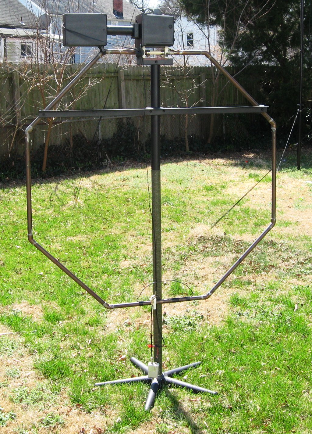
This small transmitting loop measured about 8dB worse than the 1/4λ vertical, models suggest 4dB. Coupling to masts is probably a big source of error here.
Once you've got the test setup running and you're swapping antennas back and forth, it's really easy to grab a few more antennas if you have them laying around and you use some care in interpreting the results. One antenna I had laying around was my small transmitting loop, pictured above. This is a pretty nice antenna, a four foot octagon built from 3/4 inch (0.870 inch OD) copper tubing with a Jennings UCS-300 vacuum variable and remote motor drive. With the pinger at location #6, the furthest one out, I took the 1/4λ and short verticals down and put the magloop up instead, tuned to resonance at 7372.8 and oriented to get maximum signal from the pinger. I mounted it at a height that put the top of the magloop at about where the top of the short vertical was (one more military fiberglass mast section higher than in it is in the picture). That makes the magloop and the short vertical as installed very similar in overall physical dimensions. The magnetic loop clocked in just under 7dB worse in raw field strength compared to the small vertical, and 8dB worse than the 1/4λ vertical. However, the EZNEC prediction for that is only about 4dB worse than a 1/4λ. There are several issues here, and some preliminary investigations of the Moxon masts' interaction with the magloop suggest that a magloop/quarterwave A/B test is not possible in my backyard without further work, like detuning the masts. I may be able to explain the difference with some detailed models like the investigation about masts further down this page. The magloop coupling to masts is more complicated and different enough from the verticals' coupling to cause problems.
The magloop still doesn't fundamentally need ground radials (though they were still there, so it was probably deriving some benefit from them) and mine continuously covers 5-21.5MHz, no going outside to change a tap. It's a sweet little antenna. I haven't tested it at higher power but the capacitor should allow me to run several hundred watts. But for raw performance and performance to price ratio on 40m, 30m, and 20m, my new three meter vertical seems to be noticeably better.
Other Measurements: Influence of Masts
The field strength plots in the last section show that the relative field strength of the two antennas was not very dependent on the measurement location, except in a way that was predictable in that region of the near field. However, the ABSOLUTE field strength at different parts of the yard varied a fair amount, and it varied with time as well. Shown below are plots for locations 1, 2, and 3.

The field strength arbitrarily normalized to Trial #7 for both antennas.
The clump around Location 1, 0dB are trials 7, 8, and 9, and it's clear that things changed with time or a variable I wasn't controlling from trials 1 and 2 (higher signals in location 1). I do think it's possible, however, that Location #3 was affected in absolute field strength by the presence of my 20m Moxon mast. To investigate this a little, I modeled the two masts, grounded through 10 ohm resistors (ground rods + bonding wires, no radials):

Far field pattern for the vertical with two parasitic masts.
It is very likely that the overall variation is even more than this, and this far field pattern would predict location 2 and location 3 to be closer than they are. But the model at least suggests an important effect, which is probably exaggerated when the test dipole is so close to the 20m Moxon mast as it was in location 3. I would need to take a lot more data to analyze this further, but I think there's an important lesson in it. Whatever the reason for the increased FS in trial 4 at location 3, it affected BOTH ANTENNAS about the same. This kind of thing is to be expected to a certain extent. If you have two antennas of similar characteristics, like two verticals for the same band, they will have a tendency to excite their surroundings in a very similar way.
It's like swapping in two different driven elements on the same yagi. You might change things a little, especially if one is a lossy construction, but the pattern of the yagi won't change. Neither will the pattern of my entire backyard when driven by a vertical at the test location. The pinger near the mast couples a couple dB more strongly into the antenna under test, but it does so the same way for both antennas. This, I think, is a good example of how the substitution A/B testing is a good technique. You hold EVERYTHING equal, including perturbing influences in the environment, and that gives decent differential field strength results even if there's some coupling to objects that enhances or detracts from the absolute field strength. HOWEVER, as the preliminary magnetic loop results suggest, you can't always try two antennas with very different field configurations and get good answers. Two different verticals? No problem. Two different magloops of similar physical dimensions, or identical if you're just trying different capacitors? No problem. Magloop vs. vertical? Perhaps that's a problem. Someday I might try to measure and choke off currents in the masts and see if I can sort this out more, but that's a project for later.
Conclusions
So here it is. Three whole bands, just a little bit of tap switching, superb performance, easy to understand. I feel good about my solution to the continuous tuning problem on 40m. It's simple and effective. And I didn't make something that's impossible to analyze or understand. It's just a simple top loaded vertical. It's easy to re-design for another band, like if you want one for 160m or the enormously wide 80m band. I see so much creative energy poured into designing electrically crazy antennas that maybe could be redirected into creatively designing understandable antennas. Sometimes it's because people are actually playing with antennas hoping to get rich, and my message will not get through to them. But I hope I can convince some other people that there's a lot of room for creativity within the confines of electrically boring antennas.
Revision History:
9/11/2011: Original...
9/15/2011: (?) Some revised small comments, magloop claimed to be 7dB down from 1/4 wave.
9/20/2011: Magloop caption, FS discussion and mast interaction discussion revised to reflect preliminary studies of
Moxon mast interaction.
10/01/2011: Added note about wire construction (vs. tubing)
requiring a larger
loading coil.
11/22/2011: Shortened introduction.
1/20/2019: Substantially shortened introduction.