Inductor Q Measurements - Wet Coils and More

[Home]
[Shack]
[Projects]
[Tech Topics]
Introduction
When I built the Flex Vertical and tested it, it was clear it had good efficiency. In the end, it was just a bit worse than 1dB down from a 1/4λ vertical. If I were only interested in using it, that would be the end of the story. In fact, if I were only interested in using it, I would have been done with the story after I worked V55V the first night I fired it up. But a lot of the project was just to try to sort out some ideas about short verticals. One part of the testing in particular left me with a question I needed to answer. I sprayed the antenna down with water to check for detuning, etc. and lost 4dB of signal in my field strength tests. I measured the base resistance at resonance without the shunt coil during this test and found it had gone from about 6 ohms to about 12 ohms!
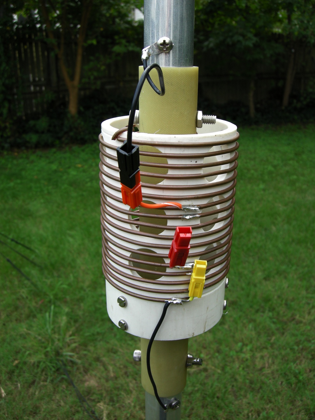
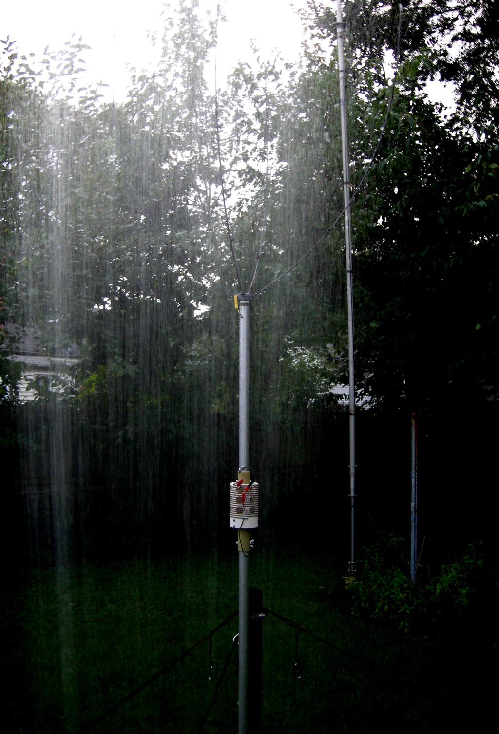
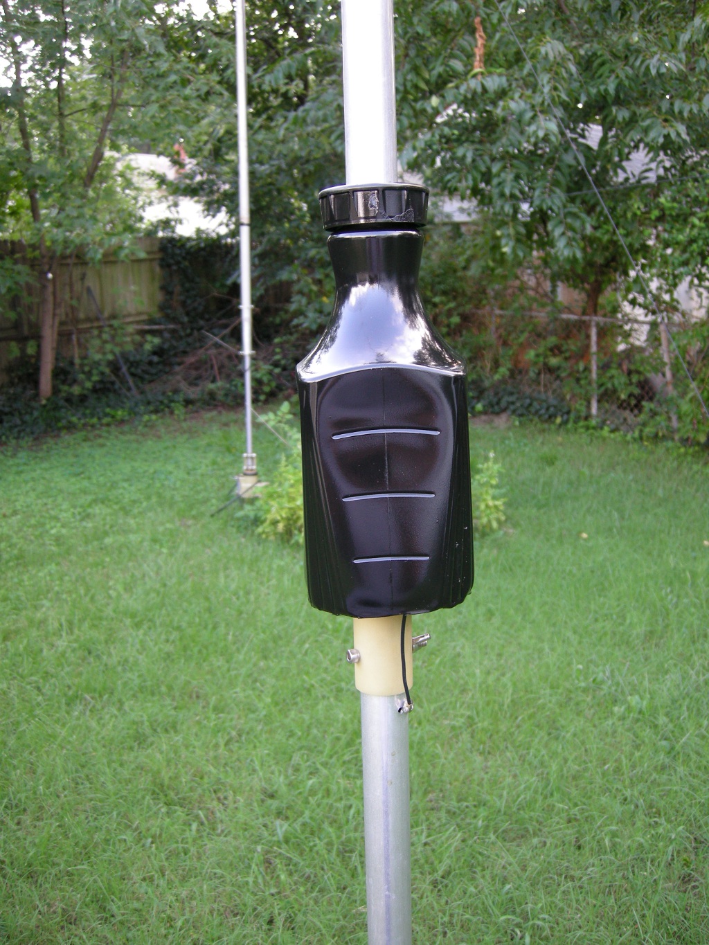
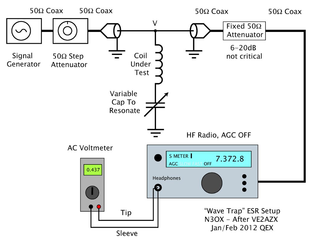
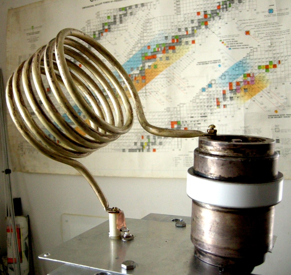
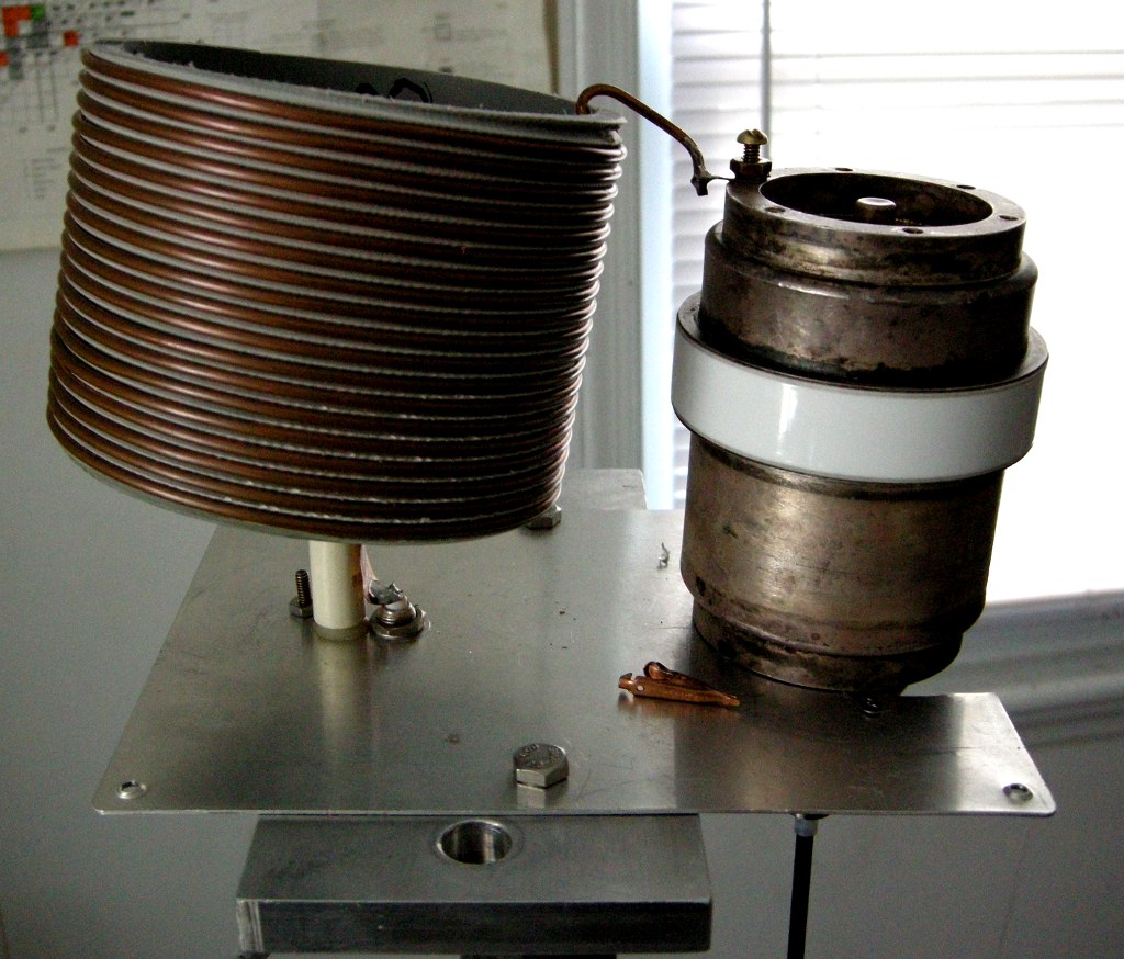
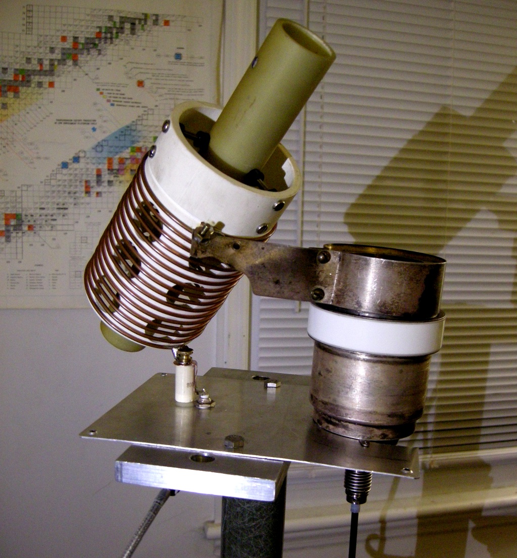
The loading coil (left) and the "simulated rain" test that cost 4dB (center), and the practical juice-based solution (right).
I guessed that the inductor was at fault and checked that first. I blew the water off it with compressed air and the antenna's base resistance and field strength immediately came back very close to the dry values, and a little bit later (after some evaporation, I guess) they came completely back. The easy practical solution was to build the coil cover pictured above. But I was a little surprised the size of the water's effect and wanted to investigate it a little more on the bench to see the effect of water on coil Q. I dabbled around with Q measurements a little bit, including trying a scattering setup like that used in the coil self-resonance tests done by G3YNH (PDF Link). But I didn't really get going on the project until I read the article by VE2AZX in the January/February issue of QEX. Jacques outlined a number of methods for measuring the Q and series resistance of inductors, one of which struck me as particularly simple and suitable for taking a lot of data relatively quickly. The idea is straightforward. You try to short out the signal passing through a 50Ω (or other known characteristic impedance) system using a series resonant circuit made of the coil under test and a high Q capacitor.
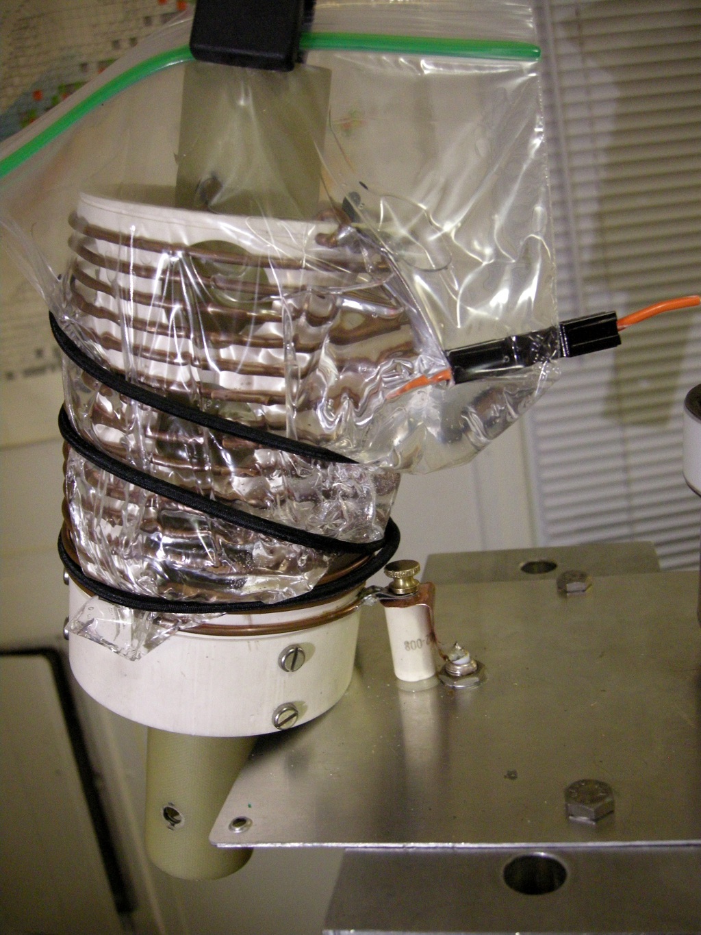
Experimental Setup
A series resonant circuit "shorting out" the signal is the idea behind a simple "wave trap" or notch filter that is very useful to solve interference problems from a single strong local station. In fact, I have one sitting here in the shack that I built to help cut out interference from a CBer neighbor. But the cool thing about the wave trap circuit that we'll use to measure Q is that the ultimate attenuation you can achieve at wave trap resonance is directly related to the small resistance of the real-world LC circuit. A perfect lossless LC circuit would be a dead short at resonance and would give infinite attenuation. A real LC circuit has a small resistance, labeled R in the diagram below. The generator below is terminated in its characteristic impedance Z0, here 50Ω, and the voltage across the termination is measured. This voltage we'll call Vu. Then the LCR circuit is connected as shown below and tuned for minimum indication on the voltmeter. This will happen at resonance, so let's call this voltage Vr. The lower R is, the smaller Vr will be.
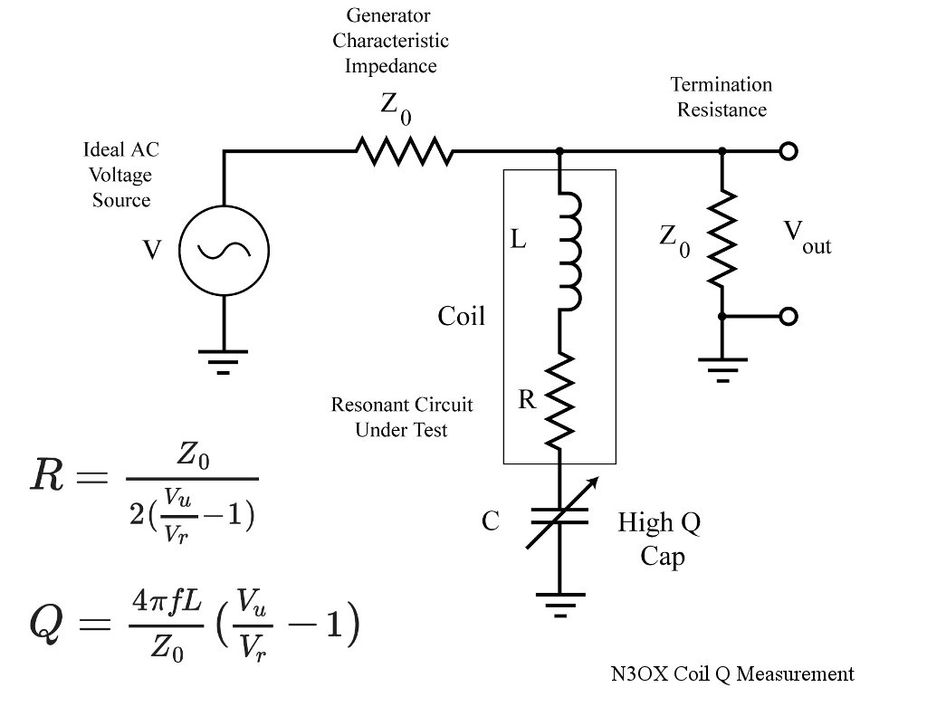
The circuit for measuring the series resistance of a coil and calculating the Q. Vu is Vout with the series LCR disconnected, Vr is Vout at resonance.
The resistance R can be calculated. When you measure the unloaded/unconnected voltage Vu, the voltage appearing across the termination is half the generator voltage. You are measuring the generator voltage through a voltage divider made up of two equal resistors of resistance Z0. When you attach and resonate the LCR circuit, you form a different voltage divider where you're measuring across the parallel combination of Z0 and R. The formula for R in the figure can be derived from the ratio of the two voltages. If you want to see where the formulas come from, here's the full derivation where I "show all my work" to make it easy to follow along: coil_ESR.pdf. If you know the inductance L, you can calculate the Q using the formula above, which is just Q = XL/R.
If you don't know the inductance, you can measure it with an antenna analyzer. In some circumstances it's better to measure the capacitor you needed to resonate it. For coils that are too large to measure, a calculator like ON4AA's inductance calculator can be useful. It's important to be a little careful with big coils that you're not running them near self resonance, but one nice thing about this method is that it's a bit agnostic about coil self-capacitance. You can take the coil as you use it in your antenna, lash it up in this sort of test, and measure the resistance you're inserting in your antenna (minus a little bit for the capacitor, but a capacitor can be extremely high Q compared to a coil). The resistance is really what you care about with "high Q coils," the resistance you're inserting when you install your actual coil, whether or not its self-capacitance is making any difference to its Q.
OK, so we have a way to measure the equivalent series resistance (ESR) of a coil as long as we can measure some RF voltages. How do we actually do that in practice? VE2AZX in his article makes the point that you need to use a frequency selective voltmeter to do this because your signal generator could have harmonics that you do not attenuate at all with this method. Plus, depending on the output of your available signal generator and your voltage measuring tools, you might find that the voltage Vr at resonance is so small it's hard to measure reliably with simple equipment. Luckily, most of us already have a pretty nice frequency selective amplifier and frequency downconverter. I decided to use basically the same setup I used to measure field strength to measure the attenuation of my wave trap, using my rig with the AGC off and DMM as a nice linear, selective RF voltmeter to measure relative RF voltages.
The actual voltage measuring implementation using a signal generator, some attenuators, my rig, and a DMM.
My signal generator is an inexpensive USB controlled unit from Softmark based around an Analog Devices AD9850 DDS chip. It only puts out about -11dBm into 50Ω at full output. This is significantly more than enough for many "reciever level" tasks; it's about 63mV, which is something like S9+62dB if you believe the 50μV "standard" for S9. But it's certainly not enough to do direct voltage measurements. In these experiments, the signal could be attenuated down to as little as 400μV. But that's still a very loud signal as received by a HF receiver. As such, there needs to be a good bit of attenuation in the system, but this is useful to make sure the source and load impedances are 50Ω. It's never a good idea to assume that your receiver is 50Ω input impedance, so an attenuator on the RX input is a good idea. I used a small Tektronix scope attenuator I have for that. It's good to put an attenutator after your signal source as well. A good lab source with 50Ω output impedance will act exactly like its Thevenin equivalent, but other available signal sources like an antenna analyzer, a homebrew crystal oscillator, or a clock oscillator chip may not. I used a 50Ω step attenuator on the output of the signal generator to knock the signal down about 40dB, which also neatly assures that the signal generator is always working into 50 ohms.
A step attenuator in the signal chain isn't strictly necessary, but it's a nice feature to check the linearity of the radio/voltmeter system. To measure high Q coils you need a pretty big linear range: in some of these tests the attenuation was as much as 40dB. Clicking the step attenuator through 10dB steps to increase the attenuation with the LCR disconneced allows you to make sure your voltmeter readings are tracking correctly with the attenuation. If you can't do this step, listen to the signal coming from your radio very carefully and adjust everything so that you can't detect even a bit of audible distortion when the LCR setup is disconnected. The good news, I suppose, is that if you don't achieve the BEST dynamic range you will UNDERESTIMATE the coil Q, which is much less dangerous to your eventual transmitted signal than thinking your coil is less lossy than it really is. In order to reduce errors from capacitor ESR, I used a Jennings 20pF-2000pF vacuum variable I had to do these tests. This was also nice because the capacitor can be used to resonate the inductor over a wide range of frequencies. A picture of the actual LC test jig is shown below.
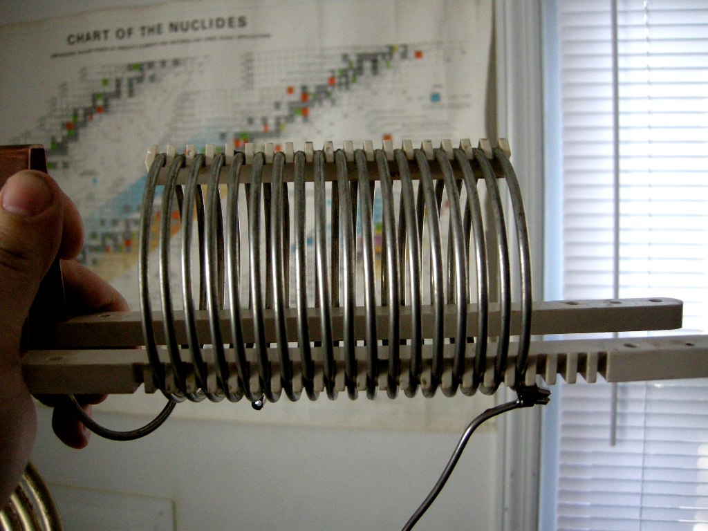
The Flex Vertical coil, including Powerpole connection, resonated with a Jennings CVCA-2000-3S vacuum variable.
Coil is 16t 10AWG (2.5mm) bare copper wire on a 3.5 inch (89mm) form, 0.25 inch (6.35mm) pitch. For the "wet" tests it is tapped at 10 turns.
The bottom end of the inductor is connected to the center conductor of a BNC that's installed in the ground plate. The top end is connected to the top of the capacitor through the actual Anderson Powerpole tap scheme I use on the real antenna. The bottom of the capacitor is grounded to the plate which helps minimize hand capacity effects. To further reduce the effects of surrounding objects (without a big copper box) the whole LC circuit is mounted on a stand that puts it above head level when I'm sitting down and a long fiberglass shaft is used to turn the tuning shaft. I can measure the effect of my hand a foot away from the top of the coil at resonance, so it's important to be careful to keep the coil away from stuff.
Wet Coil Data
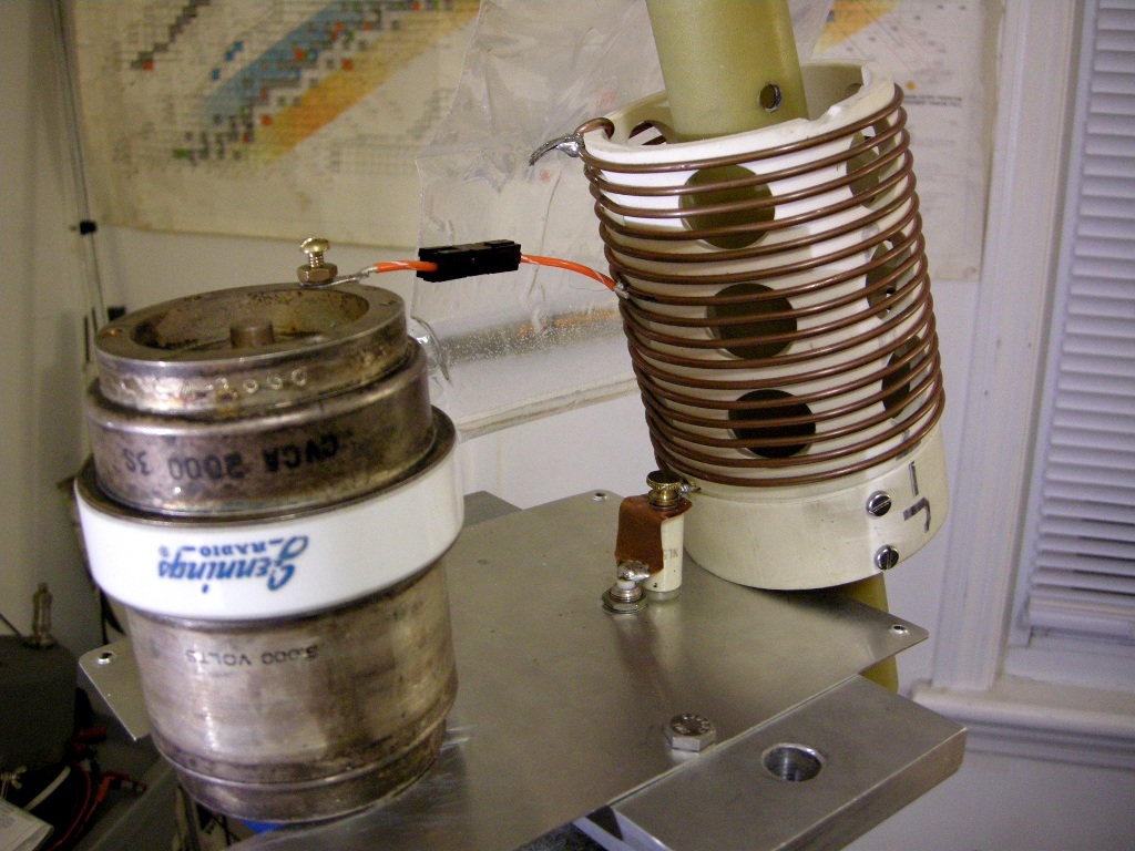
Now on to the results. We'll start with the main point of this article, which is the presence of water. I wanted a way to bring water near the inductors in a very stable way that wouldn't change as I did the measurements. I also kind of wanted to sort out the effects of the presence of a lossy dielectric from the effects of an actual conduction path. So I decided to start by putting ziploc bags of water near and on the coil. The polyethylene bags should be good insulators, preventing conduction, but allowing the lossy dielectric effects of the water to show through. Here are photos of the two water bag configurations, just hanging halfway up the "active" part of the coil on the left, and tightly bound to the coil by some elastic cord on the right:
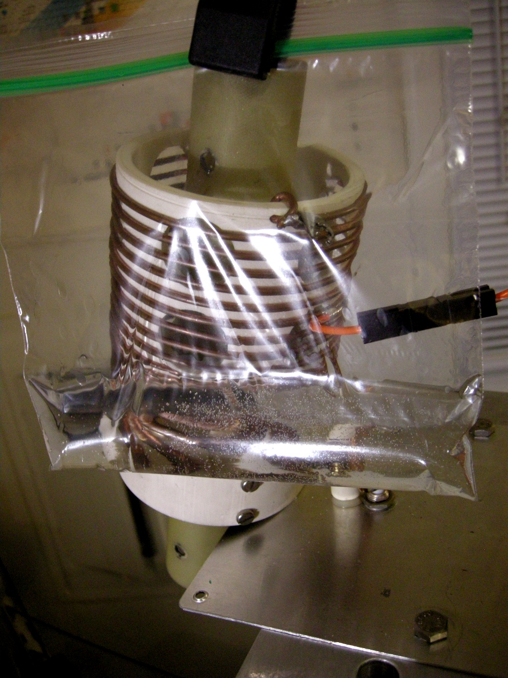
"Water bag 1" setup (left) and "Water bag 2" setup (right). Not pictured is the "naturally wet" setup, which I made spot measurements of.
In both cases it's the same bag with exactly the same amount of water, just in more intimate contact with and distributed differently on the coil in Case 2. These aren't very natural situations, so I also did a measurement of a "naturally wet" coil where I just sprinkled the coil directly with water. More on that in a bit. Here's the data for the two water bag cases. First we have the calculated Q assuming a fixed equivalent inductance of 7.5μH.

Coil Q calculated for the dry coil and for the "Water Bag 1" and "Water Bag 2" cases above.
A fixed 7.5μH inductance does not seem to be quite right for the 40m band. There's some kind of important self-capacitance effect even in the dry case. I don't have a good model for this, and ON4AA's calculator gives no help there: it's possible that it has something to do with the PVC coil form increasing the self-capacitance. But that's not really the point of this plot. What is really striking is the drastic reduction in Q brought about by just putting a little ziploc bag of water near or on the coil. The "water bag 1" case is probably noticable but usable. The "water bag 2" case is a disaster. It is perhaps not the best to look at the Q here, because it has some important assumptions. It doesn't take into account the shift in reactance the coil will have in the presence of a high dielectric constant material like water. There was a small tuning change and I didn't take the time to measure that. A less complicated way of looking at it is to just look at the calculated equivalent series resistance:
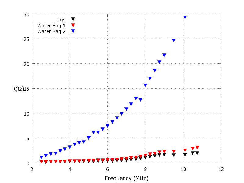
The equivalent series resistance R calculated for the dry coil and for the "Water Bag 1" and "Water Bag 2" cases above.
This actually puts things in kind of an important perspective. Very often a couple groups of hams will have an argument where one observed or measured something on the bench but the other never noticed any bad effect with an actual antenna on the air. I can imagine that happening with this data. If you look at the difference between the "Dry" and "Water Bag 1" Q, there is an extremely large effect in the sense that the Q drops to something as low as 60% to 70% of its dry value across the whole 2-11MHz range. If you're shooting for ultimate coil Q without the perspective of how it affects an antenna, the "Water Bag 1" test shows a large negative effect. But in terms of the resistance you insert in the antenna, "Water Bag 1" barely shows up on the graph, and even at the worst, it doesn't insert much more than about 2.5 ohms into the antenna. If this was a coil for a half size 40m beam or something with a few tens of ohms radiation resistance, the de-Qing provided by "Water Bag 1" equivalent wetness would probably go nearly un-noticed! It might not even appreciably raise the SWR!
Even the real-world equivalent of "Water Bag 2" adding perhaps 10 ohms of loss resistance to each coil on 40m might cause a hard-to-notice effect in on air performance. If you had a rotatable dipole with 25 ohm feed impedance loaded with these coils and matched with a 2:1 balun, the de-Qing provided by something like "Water Bag 2" would add 20 ohms, raising the SWR to 1.8:1 and causing a bit over 2.5dB loss. That's substantial but still a bit difficult to notice and probably well within the realm of "normal" behavior for a wet shortened beam! If these "wet coils" are in a modestly loaded beam that still has a few tens of ohms of radiation resistance, you just load up the amp into the new impedance and get on with making contacts! A coil Q of 30 is really pretty bad, but there are many antennas where you simply won't actually notice that kind of loss without really looking for it. I think we need to have more discussions about this, because an effect that horrifies the bench experimenter (dropping from Q=500 to Q=30) might not really be noticed by an antenna user. This is the kind of thing that easily leads to conflict, endless arguments, and mistrust of theory. Worring solely about coil losses without putting even "horrifying" losses in perspective for an actual antenna may lead antenna users to assume you're full of it when you tell them the rain is ruining their painstakingly wound high Q coils.
The lower the radiation resistance, the more important the effect is. The predicted radiation resistance over perfect ground for my antenna is about 5 ohms. If you add 5 or 10 ohms of loss resistance to an antenna with a 5 ohm radiation resistance (okay, especially while you're actually measuring the field strength), you notice! It's certainly worth having a coil cover on my antenna.
"Naturally" Wet Coil
I mentioned above that I tried a "naturally wet" configuration where the coil was sprinkled with water. I only tried it on 7MHz because I had to work fast while the water dripped off. I got Q=100 for the wettest I could get the inductor naturally, a bit over 3 ohms loss resistance. In my "simulated rain" test on the finished antenna, the measured field strength reduction and base impedance increase were more consistent with the "Water Bag 2" test, more like Q=30 or Q=50 or something. One possible explanation is that the bench test jig tilts the coil a little bit. I had a very hard time keeping water all over the coil. It all ran off to the low side of the windings and dripped directly off there. In the antenna test there was water sitting on top of all the turns and more slowly draining down the helix. At any rate, the fact that I couldn't get quite to 6Ω loss resistance in a "naturally wet" test in the shack probably doesn't rule out 6Ω extra resistance for the thorough soaking and slow drainage I saw outside. I think it's plausible that the feed impedance increase I measured was due to the water spoiling the inductor Q tremendously.
Other Coil Data
Since I had this all set up I've been measuring other coils, partially to check if I'm getting sensible answers and to assess different construction techniques. Below I've collected a variety of coils I've measured, and I will continue to add them as I measure them. I think it is useful to have a photo gallery of a variety of coils with decent Q.
Two more coils, on the left a 3μH silver plated tubing coil with Q=1020 at 7MHz. On the right, a 38μH coil with Q=610 at 1.8MHz and Q=670 at 3.5MHz
I took the nicest coil I have, the big silver plated one above left, and checked it out. I found that it was quite high Q, more than 1000 at 7MHz, provided the bolts are done up tight! I also used this coil as part of a verification of the measurement technique where I added small value resistors of 1/3Ω, 1/2Ω and 1Ω in series with this coil. I put them in series with the coil because any kind of adapters used to connect my BNC tee directly to a small resistor add enough reactance to upset the results for such small resistances. The ability to look for the zero-reactance null is really important to this technique, so it was easier to just stick the resistors in series to spoil the Q of the super high Q coil. The indicated resistances from the signal level calculations were good to 10% of the added resistances, which were also measured using a relatively high current measurement at DC.
The coil above right is a chunk of my 160m loading coil that started as a huge piece of coil stock as seen on my sixty foot vertical. I had to cut the coil down to fit the new matching enclosure when I made my new stepper driven switch and this coil is the chunk I cut off. It's wound on a chunk of gray PVC conduit that I grooved with a lathe. From time to time I've been vaguely concerned becuase the grooves are quite deep and it's not good for Q to put dielectric "between the turns." Plus I originally worried about PVC as a form for a large high Q coil. I can't test against the air-wound version without a lot of work, but the Q is a very respectable 610 on Topband and 670 on 80m, so it's not too much to worry about.
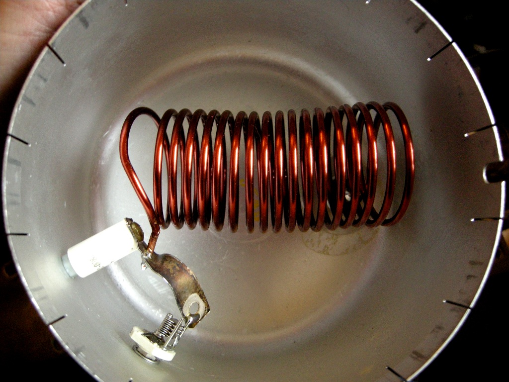
Yet more. On the left, the entire coil from the Flex, 14μH. On the right the coil out of a James Millen matchbox, 13.μH, Q=930 at 5MHz, Q=700 at 7MHz.
The coil on the right above is a big 8AWG tinned wire inductor out of an old James Millen matchbox estimated at 13μH. The Q is excellent, Q=930 at 5.5MHz and Q = 700 at 7MHz. I also measured the entire untapped coil from the Flex as one of the first set of tests I did and compared to the prediction of Q from ON4AA's inductor calculator.
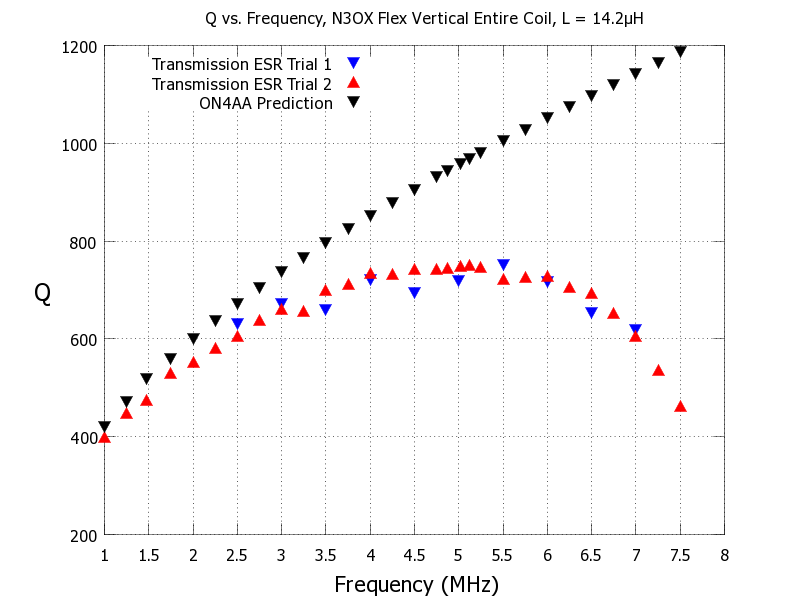
Q data for the entire (not tapped) 14μH Flex Vertical coil compared to ON4AA's calculator prediction
The prediction and measurment seem to be heading toward agreement at the low end of the plot, but they disagree badly everywhere else. It might be that this is due to the PVC form or due to some other effect that's not being accounted for in the coil models used in Serge's calculator. There's some possibility that it has something to do with common mode currents on my unshielded test setup but that is unclear at this point. More work needs to be done to understand this particular measurement.

A couple more. On the left, a self supporting 4.5μH coil, 14 turns 12AWG (2mm), 2 inch (50mm) diameter, 3.5 inches (89mm) long. Q = 570 on 40m and 400 on 20m.
On the right the coil of large (8AWG/3.3mm) enameled wire in my CB wave trap which has a Q approaching 1000 on 10m and 15m.
For many loading and matching tasks, ordinary house wire is stiff enough to make a self-supporting coil. This is my favorite kind because it requires almost no preparation; just a form of some sort for the initial winding. I use one of those military surplus fiberglass "mast" sections to wind a lot of the self-supporting coils I make. The coil on the left above is one such coil. It's about 4.5μH and the dimensions are given in the caption. It has a Q of 570 at 7.1MHz and Q of 400 at 14MHz. When I get some more time I will make a Q vs. frequency graph for this coil.
I mentioned further up the page that I built a CB wave trap to help with some interference from a close neighbor. A picture of the interior of that device is on the left. This is a situation where Q is really quite critical, as it translates directly into dB attenuation. I measured the attenuation of this notch filter and the total ESR is about 0.6Ω on 15m and 0.8Ω on 10m, good for about 30dB on 10m and 32dB on 15m. This implies a coil Q of at least 1000 for the 8AWG (3mm) enameled wire coil pictured above left, even when it is enclosed in its shield. I suspect that the wiper of the small air variable contributes a little but perhaps not enough compared to the coil to cause too much of a difference.
RF Resistance of Braid
This last section is not exactly about coil Q but since it's using the same setup and is loss-related I figured I'd put it here. I've heard many times that braided conductor has a measurably higher RF resistance than smooth flat conductor of the same overall dimensions. Well I came across a piece of the nicest braid I'd ever seen and decided to put this to the test. This braid is beautifully terminated by clamping and soldering in two large smooth lugs and is still very shiny. I thought at first that it was silver plated but on closer inspection I think it's just bright tin. Still it's in beautiful condition and terminated very well, so it's sort of a best-case scenario for a braided conductor. The braid is about 1.5 inches (38mm) wide and 20 inches (51cm) long and about 1/16 inch (1.6mm) thick when squeezed between calipers.

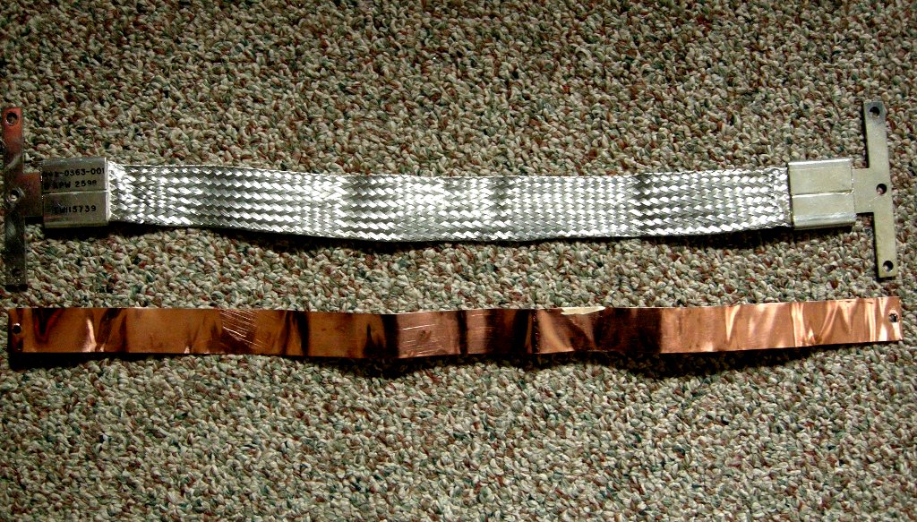
Extremely nice plated braid vs. copper strap. At 14MHz, the pictured braid has 60mΩ ESR, the narrower, thinner strap has just 35mΩ
I compared the braid to a plain copper strap the same length but quite a bit narrower and considerably thinner, pictured above left. The strap is 1 inch (25mm) wide and 0.008" (0.2mm) thick and cut to be the same length as the braid. I tested both the braid and the strap in the geometry shown above left, resonating it with the vacuum variable at 14MHz. The smooth solid strap was a clear winner even though it is narrower, thinner, and considerably lighter weight (about 7 times lighter than the braid assembly, but those lugs are pretty heavy). I measured 35 milliohms RF resistance for the strap and 60 milliohms RF resistance for the braid. That doesn't sound like much in either case, and in many applications it wouldn't be. But if you used the braid instead of strap to connect a capacitor in a magloop or if you used it as a lightning ground conductor, the difference could be quite important. As the braid gets weathered and is no longer perfect and shiny like it is here, I would expect a significant increase in the RF resistance based on what I've read.
This test also establishes an upper bound on the resistance added to the circuit by the capacitor, the bolted connections, the aluminum ground plate and the BNC connection to the feedline. The resistance of the test jig must be less than 35mΩ and it would only be that high if the copper strap were lossless. I get about 57dB of attenuation out of the smooth strap shorting setup. It's so much that I have to strengthen the signal from the generator by 10dB (by reducing the step attenuator attenuation an extra click) to get a reasonable reading on the voltmeter at resonance. With the exception of coils like the large diameter silver plated tubing one, I was measuring at least several tenths of an ohm and as much as a couple ohms RF resistance and it seems reasonable to basically ascribe that all to the coil under test.
Revision History:
2/5/2012: Original.
2/11/2012: Added braid tests, CB trap, and self supporting coil.